


Service support


Service Description
Pre-sale service
After-sales service
Service outlets
Q&A
Service
As a leading enterprise in testing machine industry, WANCE insists on R&D and innovation, keeps up with industry development, focuses on market demand, and is committed to providing professional & reliable material mechanics testing solutions.
With offices in over 20 provinces and cities including Beijing, Shanghai, Chengdu, Xi'an and Guangzhou, we have a nationwide sales & service network.
From installation & debugging, equipment maintenance & calibration, to training & technical support, we have a complete service system to provide you with professional quality service at all times.
-

 Pre-sales Support
 -

 Regional Service
 -
Regional Service
-

 On-site Service
 -

 Product Debugging
 -

 Remote Service
 -

 Customer Training
 -

 Service Hotline
 -
 Lifetime Follow-up
Pre-sales SupportRegional ServiceProduct DebuggingCustomer Training Lifetime Follow-upService HotlineRemote ServiceOn-site Service
 Regular Follow-up
Pre-sale service
Customized test plan
Engineering and technical consultation
For your specific testing requirements, the Wance technical team, with its years of accumulated professional expertise, will provide you with detailed engineering and technical consultation, reasonable machine and accessory design, control system evaluation, data collection and result analysis. Thus, seek a complete set of testing solutions that meet your specific testing requirements.

Sample testing service


After-sales Service
-
On-site Service
WANCE provides robust and reliable testing solutions, yet continuous operation and applied force may lead to wear and damage over time.
Our on-site service engineers deliver prompt & efficient support and maintenance upon request. We also assist with equipment installation and relocation, including professional disassembly, packaging, transportation and reinstallation at new premises.
01/05
-
Training
WANCE training programs aim to improve operator efficiency and optimize system performance.
Professional and fully customizable, the hands-on courses ensure your staff are fully familiar with the test system and proficient in efficient operation.
Besides standard courses, we offer customized training to meet your specific lab requirements, available at our training center or your workplace.
02/05
-
Calibration & Correction
Calibration of test equipment is essential for all labs to ensure accurate data, WANCE provides high-quality professional calibration services.
Calibration can be completed on your site or in our factory. We also offer load frame correction service to minimize data deviation.
03/05
-
Maintenance & Monitoring
Ensuring full-load operation and on-schedule completion of test projects without interruption is critical for lab management.
With years of service experience, WANCE provides comprehensive customized maintenance solutions for specific systems and components, to extend equipment life and ensure operational confidence.
04/05
-
Upgrade Solutions
With advancing technology, equipment upgrade is a cost-effective way to expand lab capability and extend the service life of existing test equipment.
WANCE offers upgrades and replacements for your test systems: mechanical components, controllers and software.
Standard software function upgrades are free of charge during the warranty period.
05/05
Service Network
Headquartered in Shenzhen, China, WANCE Test Equipment Co., Ltd. has established service outlets in Hong Kong, Japan, USA, Singapore, Netherlands, UK, South Korea and other countries worldwide.

Europe
Asia
North America
Africa
Oceania
South America

Service Hotline
Tel:+86 755 23057280
South China Ⅰ
Contact:Wu Qing
Tel:17688534216
South China Ⅱ
Contact:Yu Lian
Tel:13410663727
East China Ⅰ
Contact:Zhu Yunfei
Tel:13544017637
East China Ⅱ
Contact:Zhan Xiaobo
Tel:13472558196
Central China
Contact:Qiu Zhengxing
Tel:18306695685
North China Ⅰ
Contact:Li Hewang
Tel:15253125156
North China Ⅱ
Contact:Wang Fei
Tel:15053736933
Northwest China
Contact:Liu Fei
Tel:15249042252
Southwest China
Contact:Tang Lin
Tel:15397601854
FAQ
We have done our best to provide the questions we ask most frequently. However, if you have any questions that you haven't found answers to here, please contact us by leaving a message and submitting the form, or call our customer service hotline: 0755-2314 6660
QNo curve was observed during the test
A
Root cause analysis
Whether the power supply voltage is normal;
Check whether the sensor connector is properly connected and if there is a display of weak force value.
Check if the numeric keypade is malfunctioning or if the wires have come loose.
Is there any poor contact between the communication line of the computer and the mainframe?
Whether the parameters of the DSP system and the servo system have been adjusted properly;
Whether the limit device is functioning properly;
Whether the voltage of the switching power supply is normal;
After turning on the power of the main unit, do you immediately press the numeric keypad?
Whether all the wires inside the testing machine are tightly plugged in;
Whether the hardware parameters inside the testing machine are lost;
Open the machine cover and observe whether the server reports any error messages.
Troubleshooting
Add a voltage stabilizing power supply to ensure stable measurement voltage.
Reinsert the sensor;
Test whether the functions of each key on the numeric keypad are in good condition.
Reconnect the communication line;
Check the Settings of each parameter;
Reset the position of the limit block;
Measure the voltage at each point of the switching power supply;
After turning on the power of the main unit, wait for 20 seconds before pressing the numeric keypad.
Reinsert the wire once again.
Re-enter the hardware parameters of the testing machine;
If an Error is displayed, the server is faulty and needs to be restarted.
QThe main unit is out of power.
A
Root cause analysis
Check if the power cord is properly connected.
Whether the fuse in the power socket is present or has blown;
Has the emergency stop switch been pressed?
Troubleshooting
Check whether there are any faults in the power supply at the customer's location and the power slot of the testing machine.
Unscrew the emergency stop switch again.
QThe main unit is powered on, but the machine doesn't move
A
Root cause analysis
Whether the power supply voltage is normal;
Check whether the sensor connector is properly connected and if there is a display of weak force value.
Check if the numeric keypade is malfunctioning or if the wires have come loose.
Is there any poor contact between the communication line of the computer and the mainframe?
Whether the parameters of the DSP system and the servo system have been adjusted properly;
Whether the limit device is functioning properly;
Whether the voltage of the switching power supply is normal;
After turning on the power of the main unit, do you immediately press the numeric keypad?
Whether all the wires inside the testing machine are tightly plugged in;
Whether the hardware parameters inside the testing machine are lost;
Open the machine cover and observe whether the server reports any error messages.
Troubleshooting
Add a voltage stabilizing power supply to ensure stable measurement voltage.
Reinsert the sensor;
Test whether the functions of each key on the numeric keypad are in good condition.
Reconnect the communication line;
Check the Settings of the backup parameters;
Reset the position of the limit block;
Measure the backup point voltage of the switching power supply;
After turning on the power of the main unit, wait for 20 seconds before pressing the numeric keypad.
Reinsert the wire once again.
Re-enter the hardware parameters of the testing machine;
If an Error is displayed, the server is faulty and needs to be restarted.
QThe speed is inconsistent with the speed sent by the computer
A
Root cause analysis
Whether the hardware parameters of the memory in the DSP system (reduction ratio, lead screw pitch, maximum speed, and small keyboard control speed) are consistent with the Settings in the software;
Is the power supply a standard 220V/380V power supply?
Troubleshooting
If they are not consistent, first check whether the machine hardware parameters in the computer are correct. If they are correct, re-enter the machine hardware parameters.
An additional voltage stabilizing power supply is added to ensure stable voltage measurement.
QThe force value suddenly decreased by half
A
Root cause analysis
Whether the model of the force sensor has been selected correctly;
Has the force value calibration parameter been changed?
Has the magnification of the force sensor been changed?
Troubleshooting
Reselect the sensor channel number in the software;
Recalibrate the force value;
Reset the magnification of the force sensor.
QThe computer shows "overloaded"
A
Root cause analysis
Has the communication line between the computer and the testing machine come loose or is it in good condition?
Has the testing machine been grounded? Is there any grounding between the computer and the testing machine?
Whether the sensor connector is fully connected.
If there are several sensors, have the correct sensors been selected to enter the program?
Is it in the order of "starting the testing machine first and then entering the computer software" to turn it on and off?
Whether the calibration values are changed at will during calibration;
Has the sensor ever been bumped against?
The following methods can be used to determine whether the overload is caused by software communication or by hardware freeze.
It is caused by abnormal voltage at the switching power supply.
Check whether there is any false welding at each welding point (load channel) and whether there are any breaks at each welding point of the slingshot curve.
Is the quality of the power strip at the user's location intact?
Is the power supply at the user's location within ±10% of the normal voltage (220V/380V)?
Whether the power grid at the user's location is connected normally;
Whether the sensor is damaged;
Is the sensor model selected correctly?
Troubleshooting
Reconnect the wire;
Regrounding;
Reinsert the sensor;
Re-enter the software and select the correct sensor number;
Restart the computer in sequence and then enter the software.
Recalibrate the force value;
What is the initial force when the sensor is turned on? Is there any obvious deformation on the appearance of the sensor? Please call our service hotline at 0755-23146660.
If the testing machine is not turned off and the software is offline and then reconnected, does the computer display normally?
Add a voltage stabilizing power supply;
Re-weld;
Try replacing a power strip.
Check the power supply. If it is not normal, please add a voltage stabilizing power supply.
Consult the electrician at the user's office;
If there is an extensometer at the user's location, insert the extensometer into the sensor interface to determine whether the sensor is damaged? In case of damage, please call the service hotline at 0755-23146660.
Re-enter the software and select the correct sensor number.
QThe force value fluctuates near zero, but there is no response when applying a large force
A
Root cause analysis
It was caused by the slippage of the fixture
Troubleshooting
Consider the clamping of the fixture
QA timeout occurred during online connection
A
Root cause analysis
Whether the main unit power is turned on or if the main unit power is turned on and the network is connected immediately.
Whether it is turned on in the normal startup sequence.
Troubleshooting
First, turn on the power of the main unit and wait for 20 seconds to connect it.
First, start the testing machine, then the computer, and finally connect the software.
QAn overflow occurred when online
A
Root cause analysis
Have the force and extensometer been selected for the online window
Troubleshooting
Select the force and extensometer before going online
QThe test was stopped before the specimen was completely torn, peeled off or stretched
A
Root cause analysis
The test plan of the software is set incorrectly
Troubleshooting
Just remove the load attenuation rate
QThere is a platform at the beginning of the curve
A
Root cause analysis
The sample was not clamped.
The inlet load of the test was set too low.
Troubleshooting
Re-clamp the sample;
Set it larger and filter out this piece of data.
QNo curve was observed during the test
A
Root cause analysis
Whether the deformation sensor selected in the test plan is consistent with the main screen coordinates of the graphic coordinates;
Whether the result box is maximized.
Troubleshooting
Set consistency in the test plan;
Double-click the result box to minimize it.
QThe result data was not calculated based on the user parameters
A
Root cause analysis
Whether the standard formula for the weaving test is correct;
Whether the input user parameters are confirmed.
Troubleshooting
Modify the standard formula for the test;
After entering a user parameter, click on another box with the mouse to confirm.
QSome items in the result column have no data
A
Root cause analysis
Whether the standard formula for the weaving test is correct
Troubleshooting
Modify the standard formula for the test
QWhen you open the software, a software registration dialog box appears
A
Root cause analysis
Every software must be registered
Troubleshooting
Please provide the "Code" and "Number" in the registration dialog box to our company to remove the registration code. (Note that the software cannot be reinstalled at this time; otherwise, the consequences will be borne by yourself.)
QChanges to the test report template
A
Root cause analysis
Whether the template of the test report is set up or whether the name of the test plan has been changed
Troubleshooting
Reset the test report template
QThe compiled test standards cannot be imported
A
Root cause analysis
Whether this standard is placed in the "Export" folder
Troubleshooting
By exporting a standard, an "Export" folder can be automatically generated during the Powertest installation, and then the standard can be placed in it

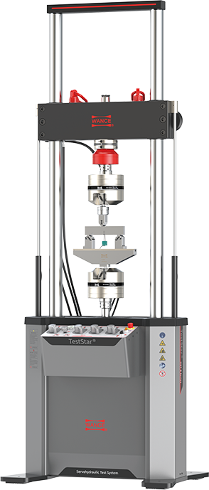
Microcomputer-controlled electronic universal testing machine - TSE series
Contact Us
To ensure that you have access to the information you need, please fill in and verify your information accurately. We will contact you via phone and text message.
Name*
Company
Phone/Email*
Address*
I understand and agree to the use and transfer of my personal information in accordance with the Privacy Policy.